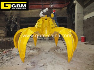
Weighing grab


The weight of the material in the grapple all acts on the shaft sensor. The shaft sensor transmits the force to the wireless transmitter box through the sensing wire, and the wireless transmitter box transmits the wire number to the wireless receiver box, and then the wire number. Connect to a computer for archiving and printing.
一、System principle introduction
1、System composition
The components of the wireless load-bearing grab system are introduced: 1 lifting rope; 2 opening and closing ropes; 3 upper bearing beams and pulley blocks; 4 lower pulley blocks; 5 lower bearing beams; 6 wireless transmitter boxes; 7-axis weighing devices; 8 buckets Body pin; 9 body; 10 wireless receiver box, other components: computers, printers, etc. (See below)
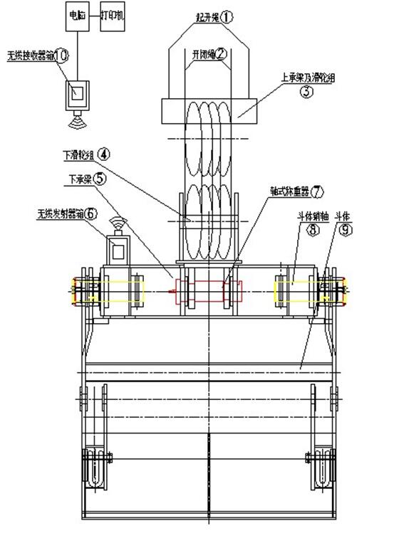
2、Principle explanation:
After the grab grabs the goods, release one lifting rope. At this time, all the weight is borne by the two open and close ropes. After the upper and lower pulley blocks, all the weights are conducted to the lower pulley block 4, and the lower pulley block 4 and the lower bearing beam 5 are The two separate components are connected via the shaft sensor 7, and the lower bearing beam 5 and the bucket body 9 are connected via the bucket pin 8. According to the force transmission, the weight of the material in the grab is all applied to the shaft sensor 7, and the shaft sensor 7 transmits the force to the wireless transmitter box 6 through the sensor line, and the wireless transmitter box 6 then transmits the line number. Pass to the wireless receiver box 10 and connect the line number to the computer for archiving and printing.
二、wireless weighing system description:
1, wireless load-bearing system components:
|
序号 |
name |
Model |
Voltage |
Qty |
|
1 |
Pin type load cell |
Ф120-30T |
10VDC |
1 |
|
2 |
Single amplifier (anti-interference) |
KQ-imuFDAL |
24VDC |
1 |
|
3 |
Intelligent display instrument (custom) |
KQ-XSB-IAH1A1 |
220VAC |
1 |
|
4 |
Wireless receiver |
|
24VDC |
1 |
|
5 |
Wireless transmitter |
|
24VDC |
1 |
|
6 |
Lead-acid batteries |
17AH |
12VDC |
2 |
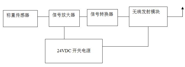
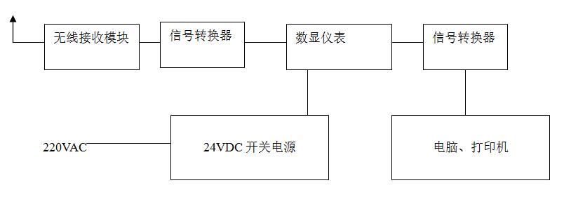
2. Operation of wireless load-bearing system: The system consists of a load cell, a signal amplifier, a wireless transmitter module, a wireless receiver module, and a weighing indicator. The wireless transmitter is equipped with two 24VDC lead-acid batteries and a switching power supply. The wireless receiver is equipped with a 220VAC power outlet and a 24VDC transformer.
The schematic diagram of the wireless transmission system is as follows:
The schematic diagram of the wireless receiving system is as follows:


 © Copyright - 2018-2021 : All Rights Reserved.